
Page 26 - ATZ11 November 2019 Professional
P. 26
COVER STORY INTERIOR
Excursion
Velocity Acceleration
Single DoF Non-single DoF
Surge -0.24 0.27 -0.30 0.29 m 0.6 m/s 6 m/s²
Sway -0.23 0.23 -0.30 0.30 m 0.6 m/s 6 m/s²
Heave -0.19 0.19 -0.19 0.19 m 0.5 m/s 8 m/s²
Roll -19 19 -22 22 ° 40 °/s 300 °/s²
Pitch -19 23 -22 24 ° 50 °/s 300 °/s²
Yaw -19 19 -22 22 ° 50 °/s 500 °/s²
TABLE 1 Technical parameters of the motion platform (DoF = Degrees of Freedom) [8] (© Volkswagen)
ond is the IPG CarMaker model, which steering wheel (Senso-Wheel SD-LC from After the adjustment of the mock-up to
is linked by a Matlab/Simulink interface. Sensodrive) can be moved together with a specific vehicle model, test persons can
On the basis of Open-CRG files, special the complete front end in the direction of trim the seat and steering wheel for their
road surfaces are transmitted to the x (in driving direction forwards/back- personal comfort within the usual lim-
motion platform using the so-called wards) and separately in the direction itations like in a real vehicle. FIGURE 5
Road Surface Interaction Server. of z (up/down), FIGURE 4. and TABLE 2 visualize the adjustment
Additionally, a seat belt pretension In addition, the steering wheel mount possibilities and an overview of all
system was integrated into the platform can be moved translationally in y-direc- adjustment distances.
in order to optimize the motion experi- tion (left/right). In the center console at
ence. This system increases the tractive the dashboard, a mount is integrated in
ADJUSTMENT PROCEDURE
force at brake maneuvers in relation to order to attach different display dum-
the acceleration value, which increases mies. So in simulations, a haptic refer- The adjustment of the mock-up for a spe-
the feeling of a brake action. Unity 3-D ence is given besides the visualization. cific vehicle project starts with the ergo-
visualization software is used for render- The driver‘s seat can be adjusted trans- nomic data which are derived from a
ing. Other road users are simulated lationally in the direction of x, y, z and defined dimensional concept or given
by Virtual Test Drive (VTD) and are rotationally within the y-axis. The ped- design data. For calculation, it will be
also visualized by Unity 3-D. For the als (Senso-Pedals Pro from Sensodrive) entered in a specific table, FIGURE 6. In
goal to have a realistic sound the H3S can be parametrized and moved trans- the following, the Catia CAD software
system of Head acoustics was integrated lational in the direction of x, y, z. is used to load the construction model
as sound simulation. Using the system, A clutch pedal is not used because of of the mock-up. Concurrently, a Visual
it is possible to simulate measured the de creased sales figures of manual Basic macro will be started to load
sounds from real vehicles as well as transmissions. Finally, it is possible to the data out of an Excel table automati-
synthetic noise of future vehicles (noise move the foot placement support trans- cally. Based on the kinematics from the
from engine, roll, tire and wind, among lational in the direction of y as well as mock-up construction model, the adjust-
other things). In spite of the open struc- the tilt angle. ment distances for the control motors
ture of the mock-up, the playback is
done by over-ear headphones (Bose
QC25 with active noise cancelling) so
that all disturbing ambient noises can
be eliminated.
MOTION PLATFORM
An electromechanical hexapod is used
to simulate motion stimuli for the test
person. The technical parameters of the
motion platform are shown in TABLE 1.
On this hexapod a weight-optimized, for
dynamics stress hardened and variable
mock-up is mounted.
VARIABLE MOCK-UP
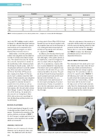
With the use of 16 motors, all relevant
elements can be adapted in their posi-
tions. The dashboard with the fixed FIGURE 4 Simulator cockpit with adjustment of dashboard and steering wheel (© Volkswagen)
20