
Page 28 - ATZ11 November 2019 Professional
P. 28
COVER STORY INTERIOR
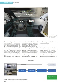
FIGURE 7 Virtual reality
in HMD visualization
(© Volkswagen)
The view matrix places the camera in during installation. When the axis of acceleration signals obtained from the
the virtual world. The HMD and MOT the head tracker and the motion base motion base, FIGURE 8.
matrices contain the HMD and motion are aligned, the matrix only contains
head tracking offsets respectively. The a translation offset. But in general it
CONCLUSION AND OUTLOOK
MOT2HMD matrix transforms the coor- might contain a translation and rota-
dinate system of the motion base to the tion. A final complication lies in the fact New requirements occur in this driving
coordinate system of the HMD. The that the sensors introduce latency and simulator concept with regard to other
view matrix is given by the vehicle sim- should be delayed or predicted such types of simulators. This is due to the
ulation algorithm (it is the position of that they align in time. Since the head combination of a variable seat position
the head in the virtual car). The HMD tracking algorithm is hardcoded in and visualization using an HMD on a
and MOT matrices are measured with unity, we determine the time shifted motion platform. Therefore, there are
physical sensors. The MOT2HMD is a motion tracking matrix using the linear already several validations done which
static matrix that should be calibrated and rotational position, velocity and show up that those developments, in the
Rendered image
Head tracking
Unity camera
Calculate to HMD axis Motion
Time shift Invert matrix
(MOT2HMD) compensation
Camera positon in the
virtual environment
FIGURE 8 Functional principle of the motion calculation (© Volkswagen)
22