Page 27 - ATZ11 November 2019 Professional
P. 27

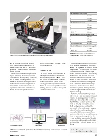
Adjustment distances pedals
                                                                                 x                   94  mm
                                                                                 y                  235  mm
                                                                                 z                   65  mm
                                                                                 Adjustment distances seat
                                                                                 x                  240  mm
                                                                                 y                  145  mm
                                                                                 z                  115  mm
                                                                                 Tilt (0°-5°)       140 mm
                                                                                 Adjustment distances steering/dashboard
                                                                                 x                  290  mm
                                                                                 y                  122  mm
                                                                                 z                  200  mm
                                                                                 Tilt steering (0°-44°)  197 mm
                                                                                 Adjustment distances foot placement support
                                                                                 y                  234  mm
                                                                                 Tilt (0°-60°)      197 mm
                                                                                TABLE 2 Technical data of adjustment distances
            FIGURE 5 Adjustment distance example of the variable mock-up (© Volkswagen)  (corresponds with Figure 5) (© Volkswagen)


            will be calculated out of the entered   models from the VW Up to VW Crafter   The combination with the motion plat-
            data. The results will be sent back to    can be represented.       form, however, creates additional chal-
            the Excel table and sent to a self-devel-                           lenges. The algorithm for tracking is less
            oped tool. This tool controls the control                           complicated. The challenging part is the
                                              VISUALIZATION
            motors directly.                                                    calibration of the HMD and the light-
              Before the real adjustment procedure   The second feature of the simulator is   houses. Cruden developed a user-friendly
            begins, a homing of all control motors   the usage of an HMD in combination    workflow for this purpose. The head
            has to be done. Subsequently, all motors   with a motion platform, FIGURE 7. Cur-  position is measured by the HMD and
            will be moved according to their axis   rent HMDs are optimized to have low   is used to adjust the camera position in
            definition after each other by the calcu-  latency at maximum power. Unity   relation to the reference camera point
            lated distances and the components of   natively provides support for different   in VR. Therefore, the rendered image
            the seat buck will be positioned. The   HMDs. So for rendering without motion   moves with the head position of the
            adjustment distances of all motors are   tracking, this can be done natively with   driver. In a dynamic driving simulator,
            chosen in such a way that all vehicle   a Unity-based renderer.     head tracking should be relative to the
                                                                                physical mock-up.
                                                                                  However, the head tracking sensors
                                                                                only work in a non-moving environment
                                                                                with the HMDs in question. Therefore,
                                                                                in this case it is not possible to measure
                                                                                the HMD head position relative to the
                                                                                mock-up directly. Instead, the static
                                                                                HMD head position is used and the
                                                                                movements of the platform are compen-
                                                                                sated. When the motion platform is
                                                                                moved, the HMD measures a different
                                                                                position (relative to the room). However,
                                                                                since no movement is expected in the
                                                                                virtual world, the movement of the plat-
                                                                                form must be subtracted from the HMD
                                                                                position at Eq. 1 before it is used for ren-
                                                                                dering:
            Dimensional concept          Calculation               Adjustment

                                                                                  Eq. 1    M   view,tracked   =  
            FIGURE 6 Procedure for mock-up adjustment: from the dimensional concept to calculation and adjustment
                                                                                                    −1
            (© Volkswagen)                                                               M   HMD     (   M   MOT2HMD    M           MOT    )    M   view
            ATZ worldwide 11|2019                                                                            21
   22   23   24   25   26   27   28   29   30   31   32