Page 56 - ATZ11 November 2019 Professional
P. 56

DEVELOPMENT  BODY


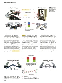
                     Dynamic experiment                                    Quasi-static experiment  FIGURE 2 Replacement
                    v = 8.89 m/s; E  = 3580 J                                 v = 0.17 mm/s    test rig for side impact
                             kin
                                                                                               beam with quasi-static
                                           Aluminum honeycomb
                                           Aluminum honeycomb at the crash block
                                                                                               and dynamic test
                                                                                               setup (© WoodCar)
                                                Side impact beam
                                               Aluminum honeycomb
                                               Aluminum
                                                on the test frame
                                              Impactor (D = 254 mm)


                                                     Energy
                                               100 %
                                                80 %
                                                60 %
                                                40 %
                                                20 %
                                                0 %
                                                  Al honeycomb at the crash block
                                                  Al honeycomb on the test frame
                                                  Side impact beam


           Two load cases were selected for   combs                            To identify the proper parameter set,
                                            combs and the bending of steel plates,
          benchmarking the wood-based side   respectively. In that way the boundary   the following method was applied: First,
          impact beam: the legislative FMVSS 214s   conditions in the installed configuration   the three vehicle models (family car A,
          and the consumer protection US-NCAP   are replicated.               family car B and SUV C) were exposed to
          pole test. To cut time- and calculation   In the development and validation of   the US-NCAP pole impact test in a vir-
          efforts in the first phase of the project,   the replacement test rig two other vehi-  tual test environment. The side impact
          a side impact beam replacement test rig   cles were considered. The three side   beams were equipped with five force and
          was developed, FIGURE 2. In the test rig,   impact beams (extracted from the one   torque transducers along the beam axes,
          the ends of the side impact beam have   OEM model and from the two open-  to obtain the forces/torque intrusion
          two degrees of freedom, namely the   source FE-models), were used to choose   curves for each vehicle. Additionally, the
          axial translation and the rotation about   the following parameters: weight of   resulting intrusions were measured rela-
          the vertical axis. These degrees of free-  impactor, thickness of the bending   tively to the total vehicle and absolutely
          dom are constrained, through the axial-   plates and energy absorption of the   to the clamping of the side impact beam.
                         aluminum honey-
          yielding behavior of aluminum honey-  combs.                        In addition, the internal energies (that


                                                       Energy absorption
                                             100 %
                                             80 %
                                             60 %
                                             40 %
                Reference steel side impact beam                                   Wood-based side impact beam
                                             20 %
                        1.18 kg                                                           1.00 kg
                                              0 %
                                                   Baseline steel  Wood-based demonstrator
                                                     Al honeycomb at the crash block
                                                     Al honeycomb on the test frame
                                                     Side impact beam
                                                         Force intrusion
                              T = 28 ms       30                                                 T = 28 ms
                                             Force [kN]  20
                                              10
                                              0
                                               0    50  100  150  200  250  300
                                                         Instrusion [mm]
                                               Wood-based demonstrator
          FIGURE 3 Energy absorption and force intrusion   Baseline steel
          of the side impact beam: comparison of the orig-  Initial crush resistance 150 mm (FMVSS214s)
          inal to the wood-based concept (© WoodCar)  Intermediate crush resistance 300 mm (FMVSS214s)
          50
   51   52   53   54   55   56   57   58   59   60   61